01
Bump diameter
Measure projected contours and 2D diameter to assess dimensional consistency.

ProductMICROBUMP / 3D METROLOGY
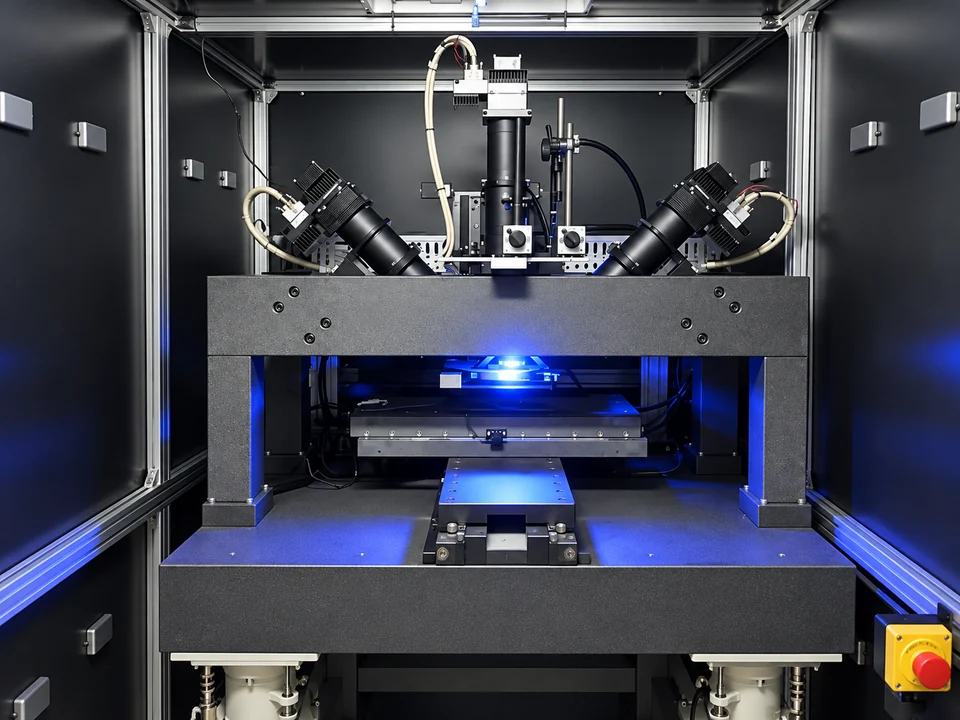
Measure microbump diameter, height and 3D shape with multiple projections and shadow-profile metrology to assess geometric consistency before bonding.
INSPECTION FOCUS
Assess dimensional consistency at the bonding interface through bump diameter, height and shape.
Measure projected contours and 2D diameter to assess dimensional consistency.
Analyze bump height from multiple projections to assess height consistency across the array.
Measure pillar, conical and pyramidal forms, with imaging conditions selected for the actual bump geometry.
IMAGING & ANALYSIS
Shadow-profile metrology extracts boundaries from spatial projections and analyzes 3D geometry. Three TDI line-scan cameras work with blue semiconductor-laser illumination and a scanning stage for array measurement.
Discuss samples and imaging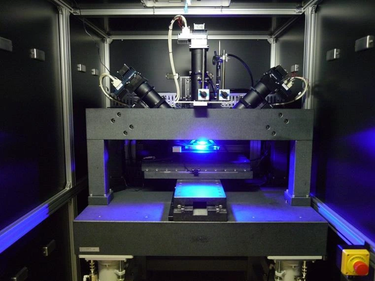
TECHNICAL SPECIFICATIONS
| Item | Specification |
|---|---|
| Wafer sizes | 6 / 8 / 12 inchSelect the configuration by wafer size |
| Minimum measurable bump | 10 μm φ |
| Camera configuration | 8192 Pixel TDI × 3 |
| Pixel resolution | 0.35 μm / Pixel |
| Measurement repeatability (σ) | ±0.1 μm / ±0.2 μmFor 2D diameter and 3D height respectively; not absolute measurement accuracy |
| Inspection time | 12 min / 6 inchFor a 6-inch wafer with 2 million bumps; varies with bump size, magnification and scanning conditions |
Pixel resolution, repeatability and absolute accuracy are distinct metrics. Confirm equipment configuration, inspection time and acceptance conditions with actual samples.
MORPHOLOGY & ARRAY OBSERVATION
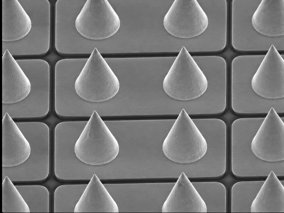
Observe the array and local morphology of pointed bumps, focusing on tip contours, spacing and shape consistency.
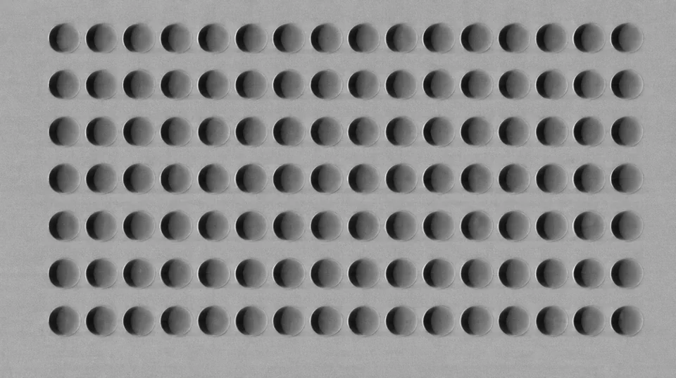
View the arrangement and contours of pillar bumps to understand the objects used in array localization and 3D geometric analysis.
SAMPLE EVALUATION
Describe the package, bump or wire geometry and the inspection questions.
Specify regions, measurements or defect classes and decision conditions.
Review imaging, handling, cycle time and output for an assessable system proposal.
RELATED PRODUCTS
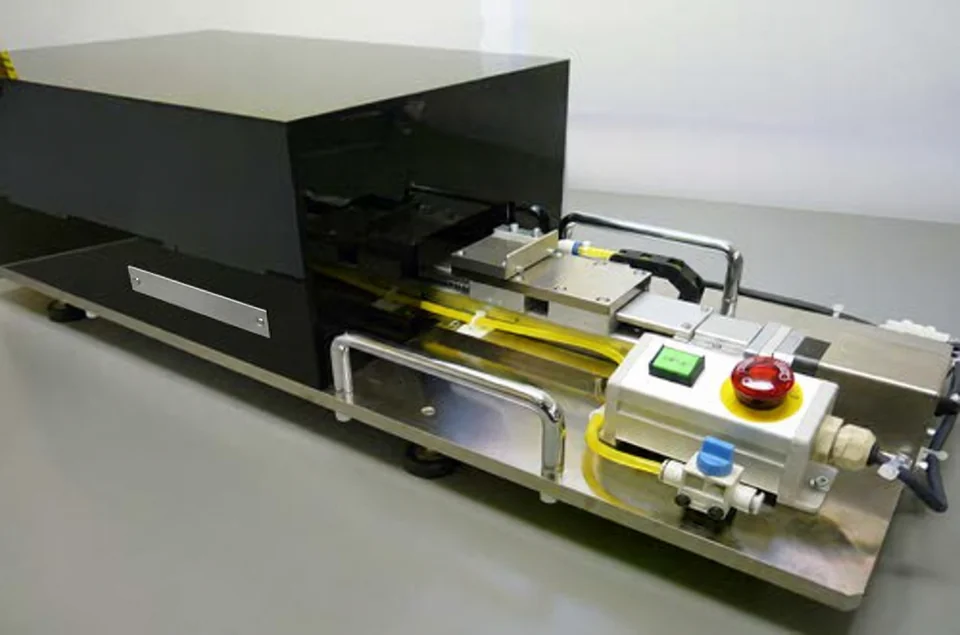
A manual solder-bump inspection system for package and flip-chip substrates, measuring coplanarity and inspecting tip profiles and attached foreign material.
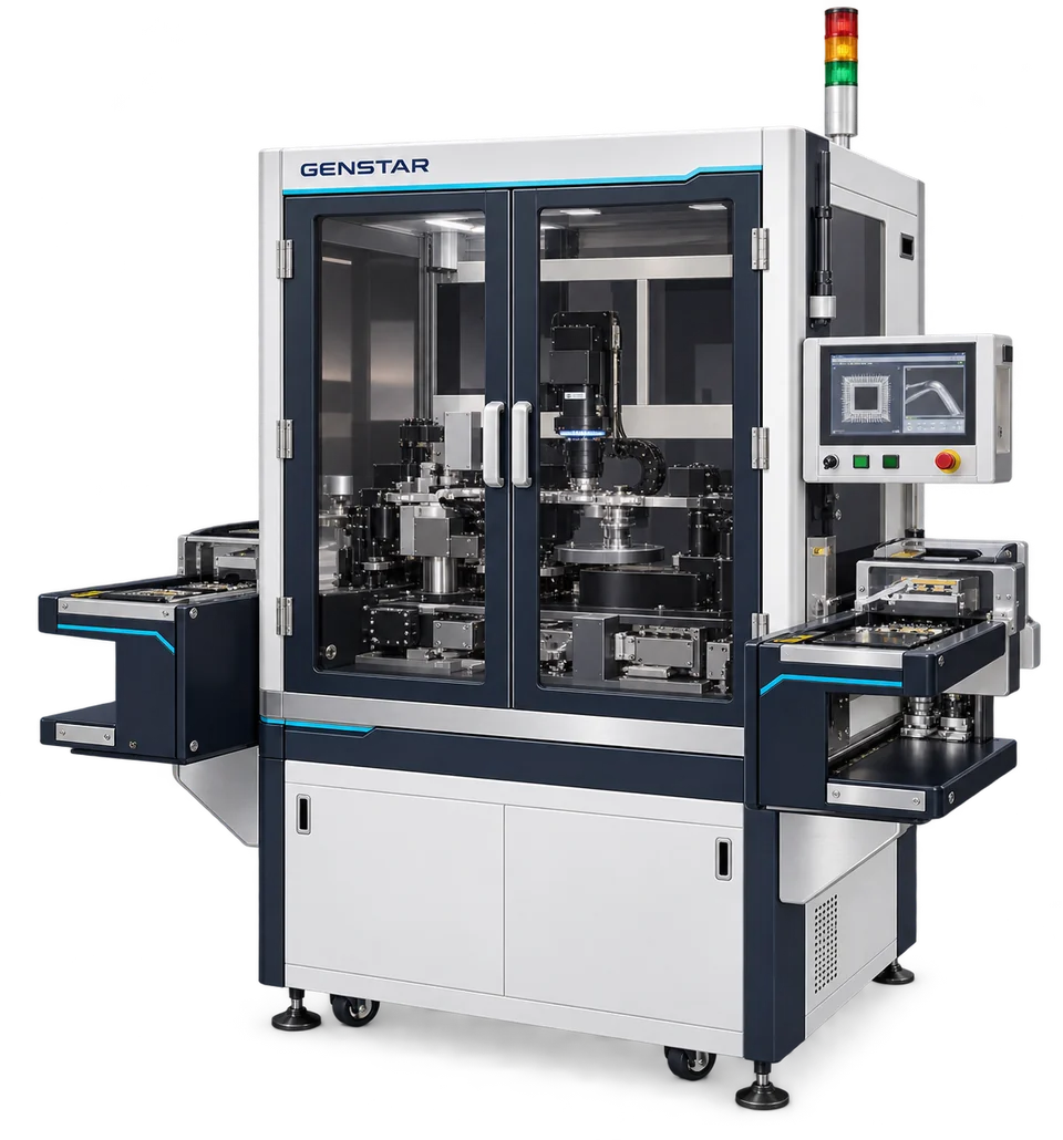
2D visual and 3D optical inspection for semiconductor packaging, covering ICs, capacitors, silver plating, lead frames, wires and bonds.
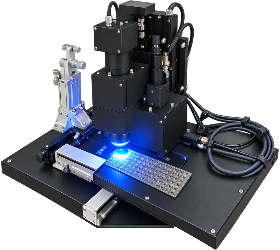
Manually load and position samples, then use microscope focus-based measurement to inspect WireBond loop height, bond geometry and position.
LET'S CONNECT
Get in touch for an initial enquiry, a technical conversation or a discussion of possible solutions.